Home/Products/Ansys Speos

ANSYS SPEOS

Ansys Speos: optical system design and simulation software

Optical simulation of illumination, visibility and sensors, carried out within the whole product including its mechanical parts. Zemax OpticStudio designs the idealized optical system; Speos places that design in a real assembly and environment and evaluates light distribution, stray light and what the sensor sees.
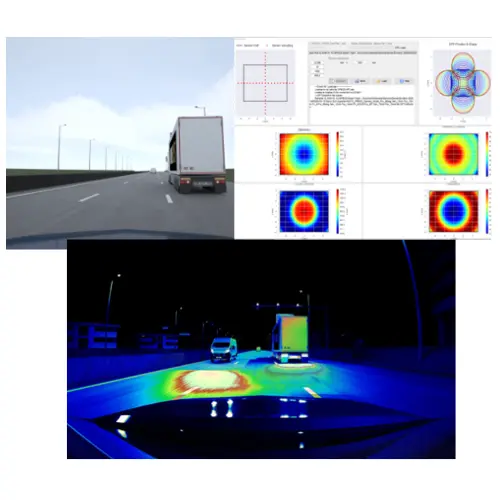
Non-sequentialLight distribution and illuminanceHuman vision

Ansys Speos analysis example, showing a road scene and sensor analysis view alongside a night-time field of view with headlamp light distribution overlaid as a luminance map

Overview

Solving how light behaves across the whole product, mechanics included

An optical simulation tool for designing optical components, illumination systems and sensors, and confirming that they hold up. It solves how light interacts with lenses, materials and the surrounding environment on a physical basis, predicting illuminance, visibility, image quality and glare before a prototype is built.

Analysis takes place inside the CAD assembly. Because evaluation covers the geometry including the barrel, the housing and the interior and exterior trim rather than the optical element alone, light leakage and reflections that only appear once parts are assembled are included.

The accuracy of its illumination simulation has been evaluated by the International Commission on Illumination (CIE) against the CIE 171:2006 test cases.

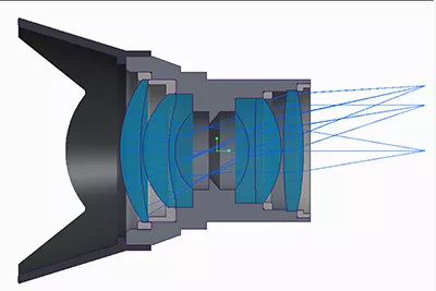
The Ansys Speos CAD environment, showing a cross-section of a lens assembly including the barrel and mechanical parts, with rays passing through the interior

What Ansys Speos gives you

Optical performance evaluated across the whole product

01

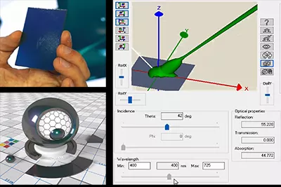
Measured material data and BRDF / BTDF / BSDF

Uses measured optical properties to reproduce scattering, reflection and transmission on complex surfaces and coatings. BRDF, BTDF and BSDF data can be used as is.

02

Sensors and human vision

Models the camera imaging pipeline and human vision on a physical basis, so you can evaluate what the sensor and what a person each receive. 1:1 luminance rendering on an HDR10 display is also supported.

03

CAD integration and multiphysics coupling

The CAD assembly itself is the analysis target. Structural and thermal analysis is handled by the respective Ansys solvers; Speos takes those results and evaluates the effect of deformation or temperature change on optical performance. Speos does not solve the structural or thermal problem itself.

An example of measured spectral BRDF data used in Speos, showing the screen where reflection, transmission and absorption components are set per wavelength from the measured sample

Where it fits

Choosing between the tools

Ansys Speos and Zemax OpticStudio cover different territory. The following is a guide to choosing.

Use Ansys Speos to

  • evaluate light distribution and stray light by non-sequential ray tracing across the whole product, mechanical parts and housing included
  • check headlamps and HUDs against both standards and real conditions
  • evaluate what a camera or LiDAR actually receives
  • check how something looks to a person, in terms of luminance and glare
  • design reflectors, light guides and lenses that meet a light distribution requirement
  • evaluate with measured material optical properties applied

Tools used alongside it

  • Detailed design of lenses and imaging optics, with aberration, MTF and tolerance analysis and imaging performance optimization → Zemax OpticStudio
  • Solving wavelength-scale structures electromagnetically → Ansys Lumerical
  • Metalens phase design through to layout generation → Photonica

The territory covered by Zemax OpticStudio and by Ansys Speos. Designing and optimizing the imaging system, and evaluating illumination, visibility and sensors across the whole product, are separate stages.

Application

Where it is used

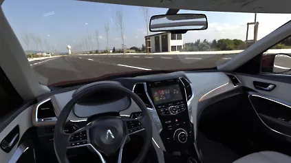
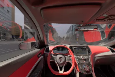
Simulation of the field of view from inside a vehicle: an example evaluating the appearance of a head-up display and interior lighting from the driver’s seat

Automotive lighting and HUD

Evaluates headlamp light distribution and how a head-up display appears. Image quality metrics such as distortion, sharpness, ghosting and parallax can be handled.

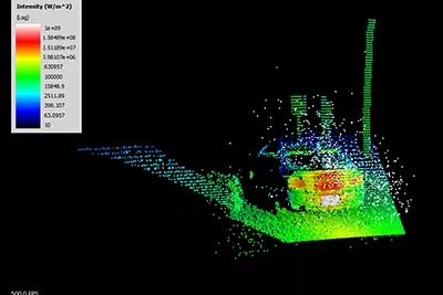
LiDAR simulation result from Speos, showing a point cloud of vehicles and structures on the road, colored by return intensity

LiDAR

It can address the emission sequence including the scan pattern, and the raw time-of-flight (ToF) signal before processing. It is also used to study sensor placement on a vehicle.

View solutions

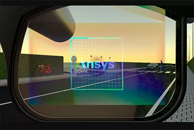
Visual simulation for AR/VR: an example evaluating a display superimposed on the field of view using a human vision model

AR/VR

Evaluates the luminance and contrast of a display on the basis of human vision. Verification on HDR displays and in VR is also supported.

View solutions

Example of an Ansys Speos optical simulation of a vehicle interior, showing the luminance distribution of red trim and a head-up display from the driver’s seat

Optical sensors

Evaluates what is actually captured in a real environment, through the camera sensor’s imaging and electronic processing. The effect of stray light on imaging performance is included.

View solutions

Inputs and outputs

What you provide, and what you get

Given a CAD assembly and definitions for sources, materials and sensors, it returns illuminance and luminance distributions and raw sensor signals.

INPUT

What you need to prepare

Three-dimensional geometryThe CAD assembly: the optical elements plus the barrel, housing and surrounding mechanical parts
Light sourceMeasured ray files, area sources, display sources, and ambient light such as CIE standard skies
Materials and surface propertiesMeasured optical properties, BRDF / BTDF / BSDF, coatings
Sensor definitionsIlluminance, luminance and intensity, cameras, LiDAR, human eye

Ansys Speos

Non-Sequential Ray Tracing

OUTPUT

What you get

Illuminance and luminance distributionPhotometric quantities and chromaticity on the detector surface
Light distributionIntensity distribution, and conformance against a standard
Stray lightIdentifying stray light by detecting its path
Sensor imagesRaw camera signals, and raw LiDAR time-of-flight (ToF) signals
AppearanceRendering based on human vision, and glare evaluation

Related capabilities

Capabilities for illumination, HUD and sensor evaluation

Speos offers the capabilities below. What is available to you depends on your environment and version.

HUD Design & Analysis

Design the imaging path of an automotive head-up display and evaluate its image quality against standards and specifications. Distortion, sharpness, ghosting and parallax are covered.

Optical Sensor Test

Evaluate raw camera and LiDAR signals in a driving environment, apply the electronic processing, and study sensor placement on the vehicle.

Speos HPC

Add compute resources to shorten run times. Both on-premises clusters and cloud clusters are offered.

Speos Labs

Edit optical properties imported from measurement equipment, or create new ones in the Labs editor, and apply them to the optical 3D mock-up.

The conditions of use depend on your environment and version. For details please Contact.

Frequently asked questions

Questions we are often asked about Ansys Speos

Questions we are often asked before adoption.

Optical Design Exchange (ODX) lets you bring a supported optical design created in OpticStudio into Speos. Geometry, optical properties and image surface information are passed across. Any surface with no coating specified on the OpticStudio side is given the Optical Polished surface property.

Add-ins that run inside the CAD system are provided for Siemens NX and PTC Creo Parametric. Geometry update is supported for Dassault CATIA V5, Creo Parametric, Siemens NX and Dassault SolidWorks. The standalone version can read CATIA, STEP, IGES and STL among others.

This uses the LSWM plugin. Coatings are solved with STACK, and diffraction grating and metalens unit cells with FDTD or RCWA, and the result is read into a Speos surface property as a data file. The handover is one-way, not a two-way coupling.

The International Commission on Illumination (CIE) has evaluated it against the CIE 171:2006 test cases, which exist to assess the accuracy of illumination simulation software.

The configuration you need depends on your application. Tell us what you want to evaluate and what you need to check, and we will propose a configuration and provide a quote.

Japanese-language support and training

We can advise on everything from setup to judging whether a result is sound. Hands-on training is also available.

Helpful to know before we talk

  • Target wavelengths and materials
  • Device structure and approximate dimensions
  • The characteristics you want to evaluate, and your target values
  • Whether you already have simulation data or measurements
  • Your expected schedule

You do not need to share everything. Whatever you are able to tell us is enough.

Try it on your own product model

The demo uses subject matter close to your own. We can also tell you the license configuration you would need there and then.