Home/Products/Photonica/Photonica Metalens Engine

PHOTONICA

Metalens design, from meta-atom to manufacturing layout

Photonica Metalens Engine is a metalens design engine that connects the electromagnetic response of the meta-atom, phase profile design, metalens assembly, analysis, and manufacturing layout output in a single tool. An assembled metalens can be evaluated on the spot, and verified as an optical system in Ansys Zemax OpticStudio.
Planned release: October 2026Release 1Verified aperture up to 200 mm

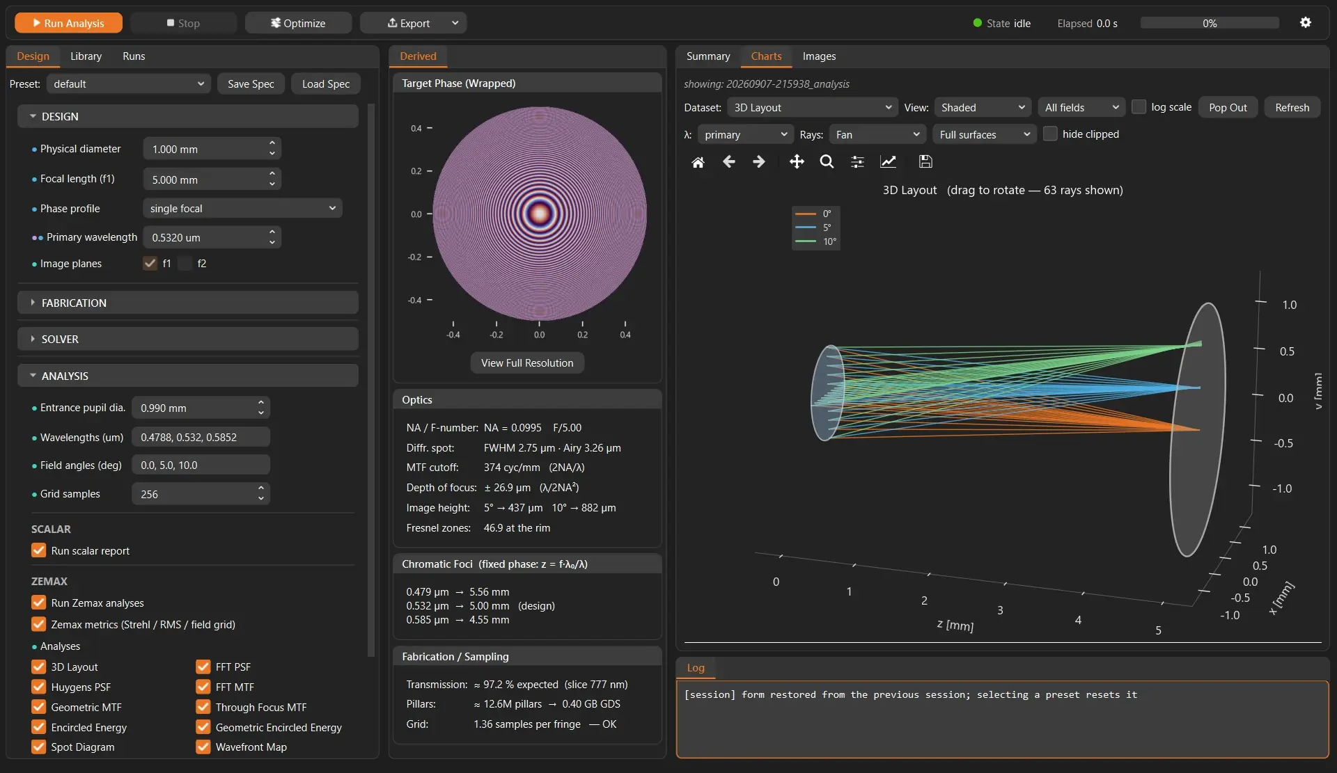
The Photonica Metalens Engine main window: design-condition panel, wrapped target phase profile, derived optics and fabrication and sampling figures, and a 3D ray layout

Overview

From meta-atom physics to manufacturing layout

Metalens design spreads across separate stages: the electromagnetic response of the meta-atom, phase profile design, assignment of meta-atoms onto the physical pitch, performance evaluation, and manufacturing data output. Photonica Metalens Engine joins these five stages inside one tool.

Aperture, focal length, design wavelength, field conditions and phase profile are defined as a design specification. For each placement point the closest entry is selected from the meta-atom library, phase is mapped to geometry, and a placement database is created. The assembled metalens can be evaluated on the spot with the built-in analysis, and in Ansys Zemax OpticStudio it can be evaluated, optimized and verified as an optical system.

Photonica ships with verified meta-atom libraries. To generate a library for a new material, wavelength or structural condition, use Ansys Lumerical to run RCWA analysis and library generation. A design is saved as a schema-validated JSON design specification and can be reproduced from that same specification. It can be run from the command line as well as from the GUI.

Design inputs

What you define

The design conditions are specified as the following items in a schema-validated JSON design specification. Optical parameters such as NA and f-number, together with the expected meta-atom count and GDS file size, are calculated before any computation starts.

Aperture (physical diameter)The physical diameter of the lens. An entrance pupil diameter for analysis can be set separately as an analysis condition.
Focal lengthThe primary focal length. A bifocal profile also takes the second focal length.
WavelengthThe design wavelength. Additional wavelengths can be set for analysis and are used to evaluate chromatic focal shift.
Phase-profile typeSingle-focus (hyperbolic), bifocal by aperture division, polynomial-corrected, or an imported phase map produced elsewhere.
Image plane / analysis conditionsWhich image plane to evaluate, the field angles, and the number of analysis grid samples.
Fabrication-related constraintsA fixed height, the pitch, and dimensional limits from the process. These feed the height-slice selection of the meta-atom library.
Selected meta-atom libraryThe meta-atom response library for the material, wavelength and geometry family (generated with Ansys Lumerical RCWA / FDTD).

Design workflow

Five stages to a design

From defining the design conditions, through the meta-atom library, assembly and analysis, to manufacturing data output, all inside the same tool.

The flow Photonica Metalens Engine handles:
Lumerical RCWA / FDTD results → meta-atom response library → target phase profile → phase-to-geometry mapping → meta-atom placement → large-scale layout generation → GDS / manufacturing data → optical-system validation

01

Design conditions

Aperture, focal length, design wavelength, field conditions and phase profile are defined as a design specification. NA, f-number, diffraction-limited spot size, depth of focus, chromatic focal shift, number of Fresnel zones, meta-atom count and the expected GDS file size are all calculated before any computation starts. The design specification is saved as a schema-validated JSON file, and any problem is reported before computation with the field name attached.

02

Meta-atom library

A meta-atom response library built from Lumerical RCWA / FDTD results is used. Verified libraries for TiO₂ pillars and holes (532 nm) and Si₃N₄ (940 nm) are included as standard. Where a new material, wavelength or structural condition is needed, run a radius-by-height sweep in Ansys Lumerical to generate and verify a library.

03

Metalens assembly

The library entry closest to the target phase is selected at every placement point on the physical pitch. Evaluation is exact, with no intermediate grid, and memory use is constant regardless of aperture. It produces a placement database together with quantization RMS, mean transmittance and per-entry usage.

04

Analysis and evaluation

The assembled metalens is evaluated with the analysis built into Photonica. The metalens design data connects to optical-system validation in Ansys Zemax OpticStudio, and verification with the vendor engine is available where required.

05

Manufacturing data output

Writes out GDSII for manufacturing, GDS for a specified region of interest, and the placement database. Once written, output is read back and verified with an independent reader.

Phase profiles and design presets

Single-focus (hyperbolic), bifocal by aperture division, and profiles with polynomial correction are supported. Phase maps produced elsewhere can also be imported, reading .npy, .csv and OpticStudio grid .dat files. During design the wrapped phase can be checked in a live preview, with full-resolution zoom.

Design presets are provided so you can start from typical design conditions such as laser focusing and beam delivery, wide-field imaging, and endoscope tip optics.

Meta-atom library

Verified libraries included, and new conditions supported

A library of the RCWA response of the meta-atoms is the reference for mapping phase to geometry.

Verified libraries included as standard

Verified libraries for TiO₂ pillars and holes (532 nm) and Si₃N₄ (940 nm) are usable from day one. Each library is verified against RCWA by an independent full-wave Ansys Lumerical FDTD analysis; transmittance agreement is better than 1% for pillars, about 2% for holes, and 0.2% for uniaxially anisotropic films.

Library generation with Ansys Lumerical

Libraries for new materials, substrates, pitches and wavelengths are generated by a radius-by-height sweep. Checkpointing and resume are supported, and further heights or angles of incidence can be added to the same library file.

Supported meta-atom geometries and incidence conditions

Pillars, holes (etched openings in a film) and rings (annular walls) are supported, and each is carried through placement and layout output in its true geometry. The library also holds oblique-incidence s- and p-polarized response and uniaxially anisotropic (birefringent) film materials; the oblique response is used through the Zemax OpticStudio link (LSWM).

Library QA and height slice selection

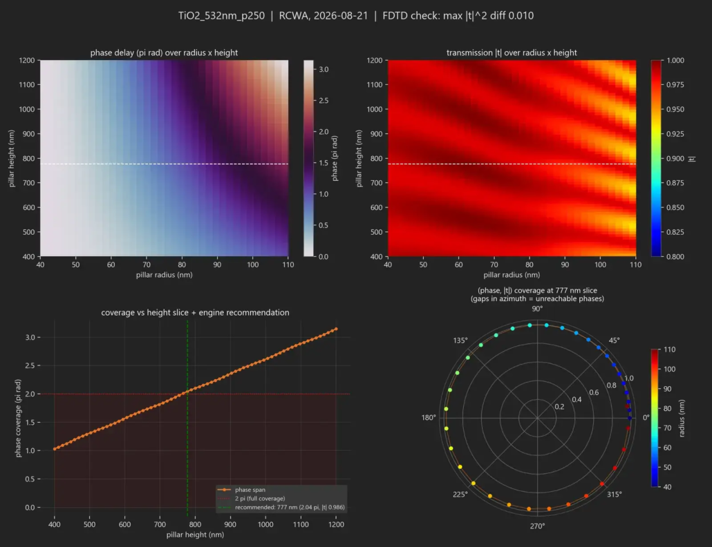
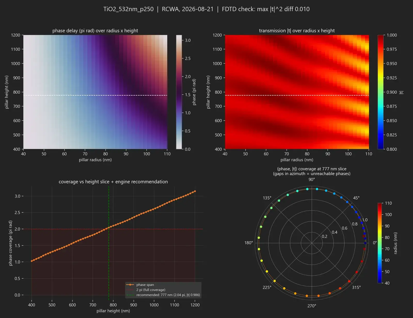
Phase and transmittance maps, coverage curves against height, and a polar coverage view are available. A recommended height slice is offered, and a fixed height can be specified where manufacturing requires it. The match between library and design is checked against file attributes, and a mismatch is detected before computation.

Photonica ships with verified meta-atom libraries. To generate a library for a new material, wavelength or structural condition, run Ansys Lumerical to run RCWA analysis and library generation.

Library selection is decided by the material, the wavelength, the geometry family (pillars, holes, rings), the pitch and dimension range, the phase coverage and the transmission. The electromagnetic response of the unit structure comes from Ansys Lumerical RCWA / FDTD analysis data, and the cross-check against FDTD is recorded in the library QA report. An example QA report is included in the example outputs further down the page.

Mapping and placement

Map phase to geometry, then verify the placement

At every placement point of the target phase profile, the closest entry is assigned from the meta-atom response library, and the placement is then verified.

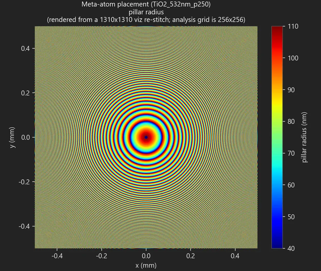
Meta-atom placement map for a 1 mm TiO2 pillar metalens: a concentric pattern showing the pillar radius assigned at each placement point

Meta-atom placement map: pillar radius assigned at each placement point (TiO₂, 532 nm, 250 nm pitch)

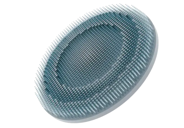
3D rendering of a TiO2 pillar metalens implementing the target phase profile, with pillars of varying radius arranged in concentric zones

TiO₂ pillar metalens implementing the target phase profile (3D rendering)

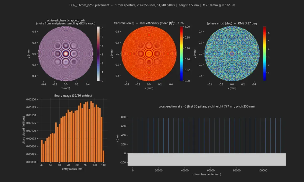
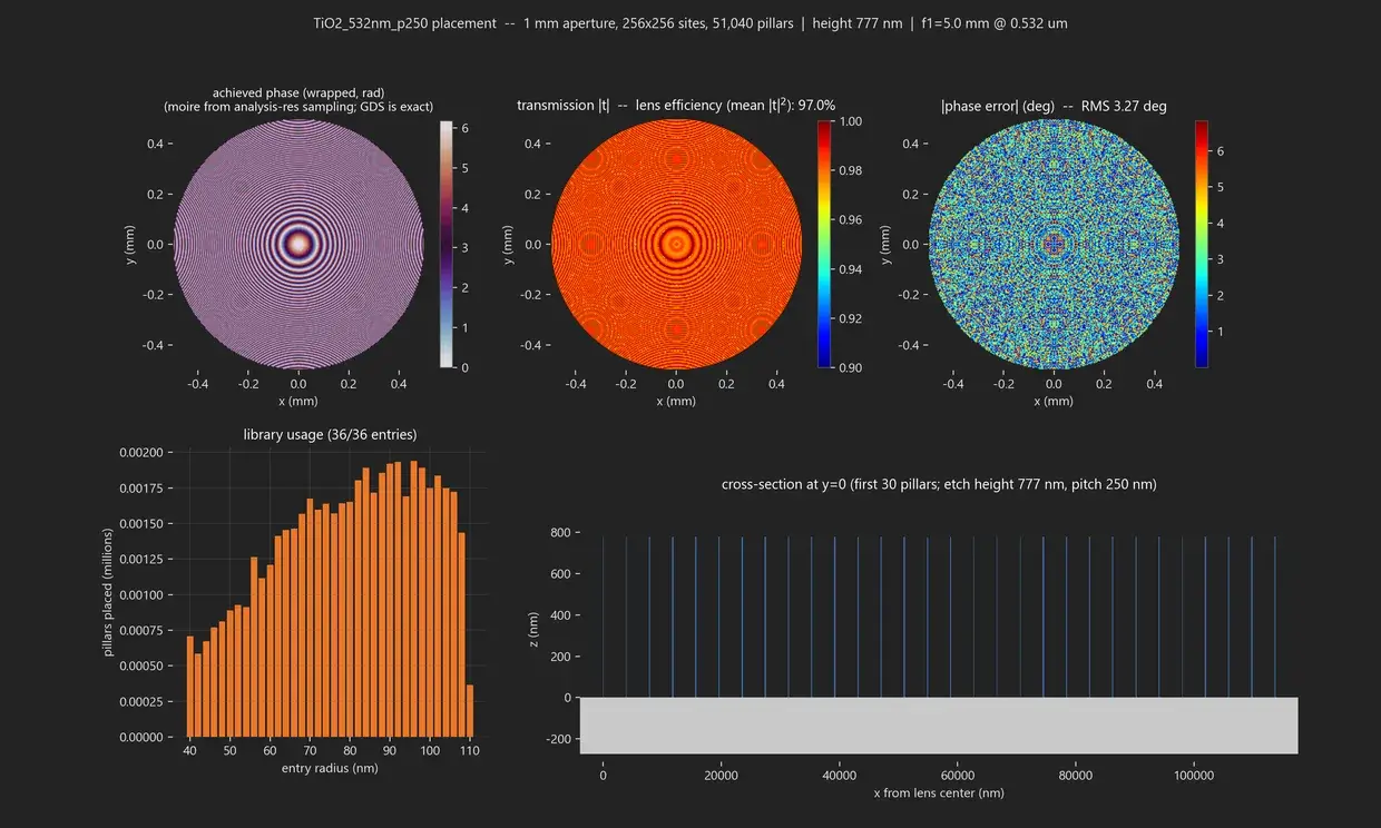
Placement verification checks the wrapped achieved-phase map, the transmission map with its mean, the distribution and RMS of the phase error against the target, the usage of each library entry, and the structure dimensions in cross-section together with the consistency of the sampling. Where the analysis-grid rendering shows moire from sampling, the GDS output still writes the placement data exactly. An example placement report is included in the example outputs further down the page.

This verification is a placement-level (design-level) check based on the meta-atom response library, not an electromagnetic analysis of the whole lens. It confirms the placement before that step.

Analysis

Evaluate an assembled metalens on the spot

For an assembled metalens, the analysis built into Photonica returns results in seconds. It plays a different role from optical system evaluation in OpticStudio, and the two complement one another.

Photonica built-in analysis (assembled lens)

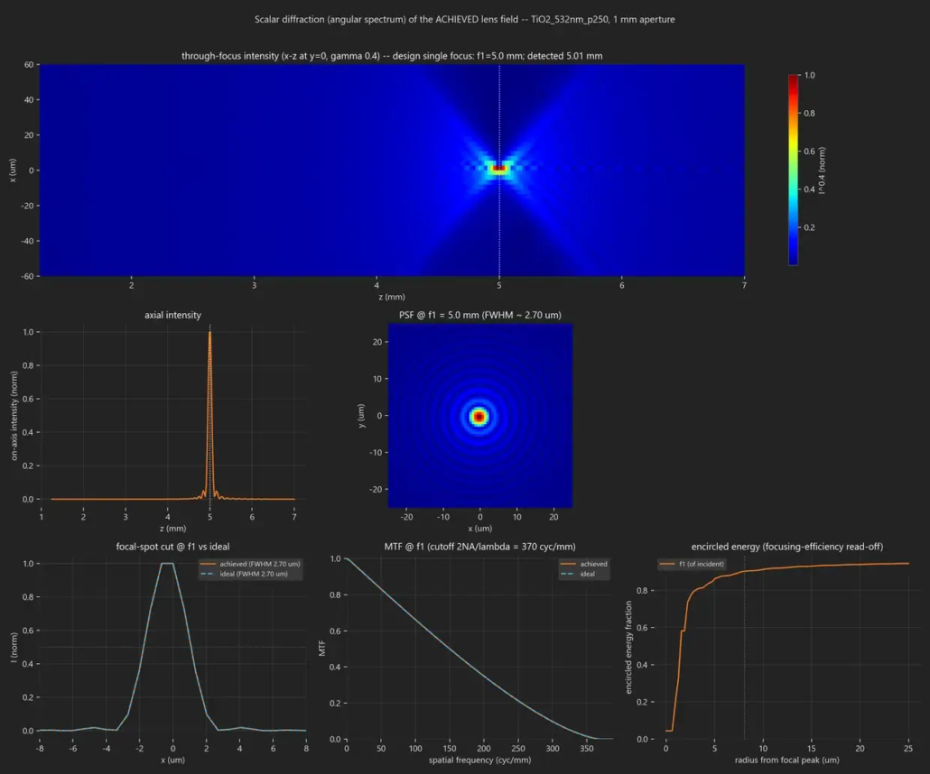
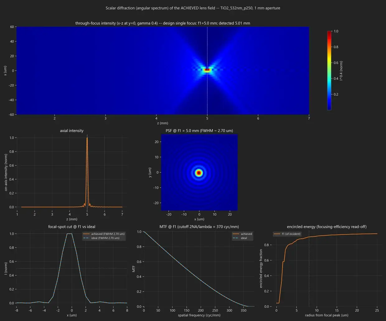
As-fabricated Strehl ratio, PSF and FWHM against the diffraction limit, focusing efficiency, through-focus intensity distribution, encircled energy and MTF, PSF against field angle, chromatic focal shift, far-field power distribution by angle, predicted focal position, placement report and cross-section information, and imaging simulation using the PSF (a USAF target, for example). It completes in seconds.

Design analysis in OpticStudio

On-axis and field-by-wavelength Strehl ratio against the design phase, Huygens and FFT PSF, FFT, geometric and through-focus MTF, diffraction and geometric encircled energy, spot diagrams with RMS radius, wavefront maps, ray and OPD fans, and a 3D ray-trace layout.

Verification with the vendor engine

The assembled lens is passed to the Ansys sub-wavelength metalens plugin and read back field by field at the angles of incidence the library characterized. Focal centroid against the design position, energy within ±10 µm, relative efficiency, and an illuminance image at the focal plane.

Where both a design value and an as-fabricated prediction exist for an analysis, the two are output side by side. The definition of each metric is recorded in the output data.

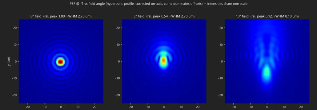
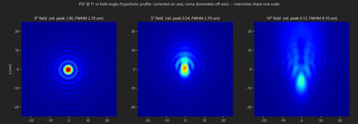
An assembled design can be evaluated with the built-in analysis, within the range of analysis outputs implemented. Through-focus intensity and PSF against field angle show how a hyperbolic profile corrected on axis behaves off axis, comparing peak intensity and FWHM field by field. For a wide-field design, that result is the basis for moving on to polynomial correction or to optical-system evaluation in OpticStudio. Example analysis outputs are included in the example outputs further down the page.

Optimization through the OpticStudio link

Analyze in OpticStudio, merge the polynomial phase correction it proposes into the Photonica design, reassemble against the real meta-atom library, then re-analyze and compare before and after. A regression guard keeps the best measured result.

Weighting can be on-axis, balanced, wide-field, or specified freely per field, and the merit function can be wavefront RMS, geometric spot, or MTF contrast at the frequency that matters for the application. By default a correction preserves the specified focal length; focal shift is merged only when it has been permitted. The saved design is not changed until you have reviewed the field-by-field before and after comparison (Strehl ratio, MTF and spot) and applied it.

What each tool does

Connecting Lumerical through to OpticStudio

Metalens design spans several tools. Each has its own role, and Photonica Metalens Engine joins the handovers into one continuous design workflow.

Ansys Lumerical
Meta-atom analysis and library generation

RCWA analysis→Material, wavelength and structure sweeps→Meta-atom library

Generates and verifies meta-atom libraries by RCWA analysis for new materials, wavelengths, geometries, heights and angles of incidence. The libraries included as standard have been cross-verified against full-wave FDTD.

Photonica Metalens Engine
Metalens design, placement and large-scale layout generation

Lumerical RCWA / FDTD results→Meta-atom response library→Target phase profile→Phase-to-geometry mapping→Meta-atom placement→Large-scale layout generation→GDS / manufacturing data→Optical-system validation

Uses the meta-atom response library generated with Ansys Lumerical, maps the target phase to geometry at every placement point, and generates the large-scale layout and GDS / manufacturing data. The built-in analysis checks the placement, and the metalens design data connects to optical-system validation in Ansys Zemax OpticStudio.
Ansys Zemax OpticStudio
Optical system evaluation, optimization and verification

Strehl ratio, PSF, MTF→Wavefront and spot→Field and wavelength evaluation→Optimization

Places the metalens in an optical system and evaluates Strehl ratio, PSF, MTF, wavefront and spot across field and wavelength, then optimizes it as an optical system. Verification with the vendor engine is also supported.

The three tools have different roles and are not interchangeable.

Manufacturing data output

Large-scale layouts, straight to manufacturing data

Starting from the placement database, it writes out GDSII for manufacturing, ROI GDS for a specified region, and handover data.

Manufacturing GDSII and ROI output

Output uses a 1 nm database unit, with layer and datatype selectable. It streams out with constant memory regardless of aperture, writing pillars and holes as circles and rings as true annular polygons. As well as the whole layout, any rectangular region can be written as detailed GDS in seconds.

Placement database and large-scale layouts

An HDF5 database recording the position, entry, radius and origin of every meta-atom is the starting point for layouts, reports and handover data. The expected file size is shown before computation, and a very large layout can be held at roughly 1/160 the size of the equivalent GDS, with only the region you need written out as GDS.

Read-back verification

Written GDS is read back with an independent reader and checked against the placement data for reference count, radius and position. Very large files are verified by a constant-memory scan of their contents.

An imported phase map is interpolated onto the meta-atom grid at output, and the sampling is checked for adequacy against the outer fringes of the design.

Part of a written GDS layout: a magnified view of the placement pattern with pillars written as circles

Part of the written GDS layout (pillars written as circles)

GDS and manufacturing-data generation

From the placement database, it generates GDSII for manufacturing, ROI GDS for any specified rectangular region, placement and layout data, and handover data for manufacturing. Written GDS is read back with an independent reader and checked against the placement data.

Whether a generated layout can be manufactured depends on the material, the geometry, the wavelength and the foundry process. Confirming the fabrication conditions and handing over the design data are covered by Design to Fabrication at the LightBridge foundry.

Dependable runs, and automation

A run history stores the design specification, results, artifacts and notes for each run, and a design can be reloaded in one click. Sessions are restored across restarts, library generation supports checkpointing and resume, progress and estimated time are shown per stage, and size and scale warnings are given before computation. Every failure returns a message with a code that tells you what to do about it, and there are machine-readable progress and error events plus a command-line interface for automation and for integration with existing systems.

Verified scale

Verified design scales

Measured in a reference environment (a single desktop workstation, with the same engine and GUI).

ApertureMeta-atoms placedOutput and time taken
1 mm12,566,345402 MB GDS / 22 seconds
10 mm1,256,636,85740 GB GDS / about 30 minutes
100 mm125,663,704,42111.7 GB placement database / about 5.5 hours
200 mm502,654,823,34541.3 GB placement database / about 30 hours

REFERENCE DESIGN

Reference design

Aperture1 mm
Focal length5 mm
Design wavelength532 nm
MaterialTiO₂
Pitch250 nm

RESULTS

Measured results

Design Strehl ratio1.000
As-fabricated predicted Strehl ratio0.967
Predicted focal position5.00 mm
Power in the design cone97% of transmitted power

Every figure above is measured in the reference environment and is not a guarantee of performance in every environment. The measured results correspond to the conditions of the reference design given alongside them.

Inputs and outputs

What you provide, and what you get

INPUT

Design specificationJSON
Phase map.npy / .csv / OpticStudio Grid Phase (.dat)
Meta-atom libraryHDF5

Photonica Metalens Engine

Metalens design engine

OUTPUT

Placement databaseHDF5
Manufacturing dataGDSII / ROI GDS
OpticStudio linkGrid Phase (.dat) / Binary 2 coefficients / .lswm / .lmap
Analysis and automation.npz / .png / machine-readable event and result data

Frequently asked questions

Questions we are often asked about Photonica Metalens Engine

Release is planned for October 2026. Even before release, we are happy to discuss the designs and workflows you have in mind.

Photonica provides verified libraries, and for a new material, wavelength or structural condition you can generate a meta-atom library by running RCWA analysis in Ansys Lumerical. Alongside the radius-by-height sweep, further heights and angles of incidence can be added to the same library file, and checkpointing and resume are supported.

Pillars, holes (etched openings in a film) and rings (annular walls) are supported, and each is carried through placement and layout output in its true geometry. The library also holds oblique-incidence s- and p-polarized response and uniaxially anisotropic (birefringent) film materials; the oblique response is used through the Zemax OpticStudio link (LSWM).

Single-focus (hyperbolic), bifocal by aperture division, and profiles with polynomial correction are supported. Phase maps produced elsewhere can also be imported, reading .npy, .csv and OpticStudio Grid Phase (.dat). An imported phase map is interpolated onto the meta-atom grid at output.

For an assembled metalens you can obtain, in seconds, the as-fabricated Strehl ratio, PSF, FWHM against the diffraction limit, focusing efficiency, through-focus intensity distribution, encircled energy and MTF, PSF against field angle, chromatic focal shift, far-field power distribution by angle, predicted focal position, and imaging simulation using the PSF.

The design phase is passed across as Grid Phase or as Binary 2 coefficients, and Strehl ratio, PSF, MTF, wavefront and spot are evaluated as an optical system. A polynomial phase correction proposed by OpticStudio can be merged into the Photonica design, reassembled against the real meta-atom library, and re-analyzed. An assembled lens can also be passed to the Ansys sub-wavelength metalens plugin as .lswm and .lmap for verification.

It streams output with constant memory regardless of aperture. Measured in the reference environment, a 1 mm aperture with 12,566,345 placements produced a 402 MB GDS in 22 seconds. The expected file size is shown before computation, and a very large layout can be held as a placement database (roughly 1/160 the size of the equivalent GDS), with only the region you need written out as ROI GDS in seconds.

Technical support from LightBridge

This is a product developed by LightBridge. We are happy to advise on everything from putting the design procedure together to interpreting the results.

Helpful to know before we talk

  • Aperture, focal length and design wavelength
  • Material and the pitch you have in mind
  • Field conditions and the metrics you want to evaluate
  • Manufacturing process constraints (etch depth, aspect ratio)
  • Your expected schedule

You do not need to share everything. Whatever you are able to tell us is enough.

Tell us the design conditions for your metalens

Let us know the aperture, focal length, design wavelength and material, along with the design scale you have in mind, and we will discuss it with you and put together a demo.