ANSYS LUMERICAL

Lumerical CML Compiler: generating compact model libraries

From device analysis and measurement results, it generates compact models usable in circuit simulation. Models for individual elements are collected into a library, which can be shared within a design team or distributed as the model library of a foundry PDK.
CMLPDKModel generation

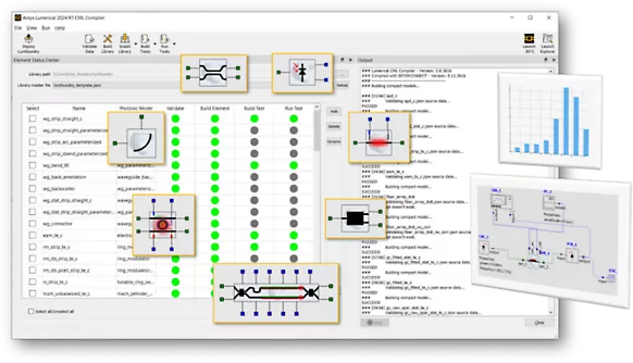
The Lumerical CML Compiler screen, listing verification, build and test progress for each element model in the library

Overview

Turning analysis results into models you can reuse

Some device analysis results, S-parameters for instance, can be read straight into INTERCONNECT. But raw data for one set of conditions is not reusable. For a design team to use it repeatedly, analysis and measurement data has to be organized into compact models that circuit simulation can use. Where needed, dimensions, temperature and bias conditions can be parameterized.

CML Compiler performs that conversion systematically. From device analysis and measurement results it generates compact models and collects them into a library.

It is used both when a foundry prepares a PDK and when a company standardizes its own device library internally. It avoids the situation where every designer has a different model.

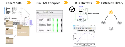
The flow for building a compact model library, showing four stages: data collection, running CML Compiler, QA testing, and library distribution

What CML Compiler gives you

What being able to reuse a model achieves

01

Parameterization

Generates models that take dimensions and operating conditions as arguments.

02

Library packaging

Several elements can be collected into a library and distributed as the model library of a PDK.

03

Verification

You can confirm that the generated model is consistent with the input data.

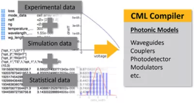
Diagram showing measured, simulated and statistical data being brought into CML Compiler to generate photonic models for waveguides, couplers, photodetectors, modulators and more

Where it fits

Where it fits, and where it does not

For some problems another method solves faster and more accurately. The following is a guide to choosing.

Use CML Compiler to

  • standardize an internal device library
  • prepare the models for a foundry PDK
  • put analysis and measurement data into a form reusable in circuit design
  • treat element dimensions as parameters
  • manage model versions

Consider another method

  • A one-off circuit analysis → INTERCONNECT read the S-parameters in directly
  • Obtaining the device characteristics themselves → FDTD / MODE / CHARGE / HEAT

Turning device analysis or measurement results into compact models and reusing them in circuit simulation.

Typical applications

Where it is used

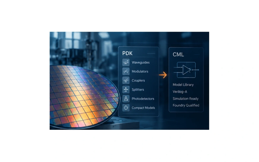
The flow for generating a compact model library from a foundry PDK, showing PDK elements such as waveguides, modulators, couplers, splitters and photodetectors collected into a Verilog-A model library for circuit simulation

Foundry PDKs

Model preparation by the platform provider

View PDK services

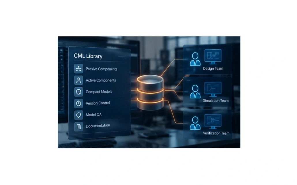
The make-up of a compact model library shared internally, showing passive and active element models, version control, model QA and documentation collected into one library that the design, simulation and verification teams all reference

Internal standardization

A device library common to the design team

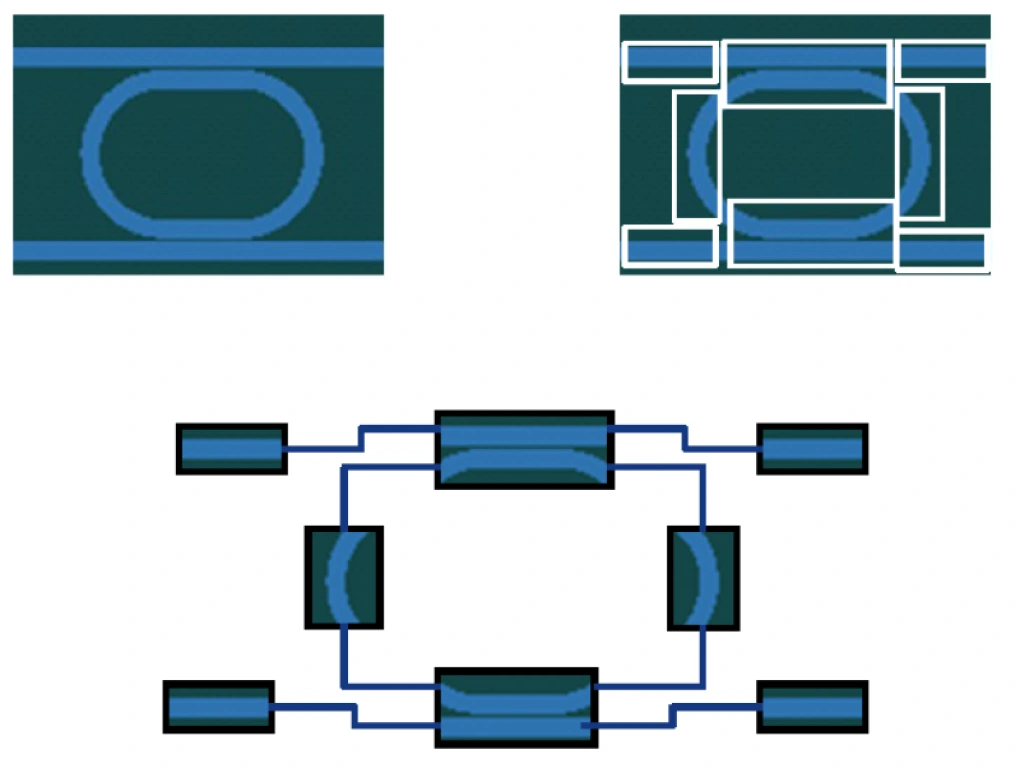
Comparison between analyzing a ring resonator in one pass with FDTD and partitioning it for integration in INTERCONNECT

Silicon Photonics

Models for passive and active elements

View solutions

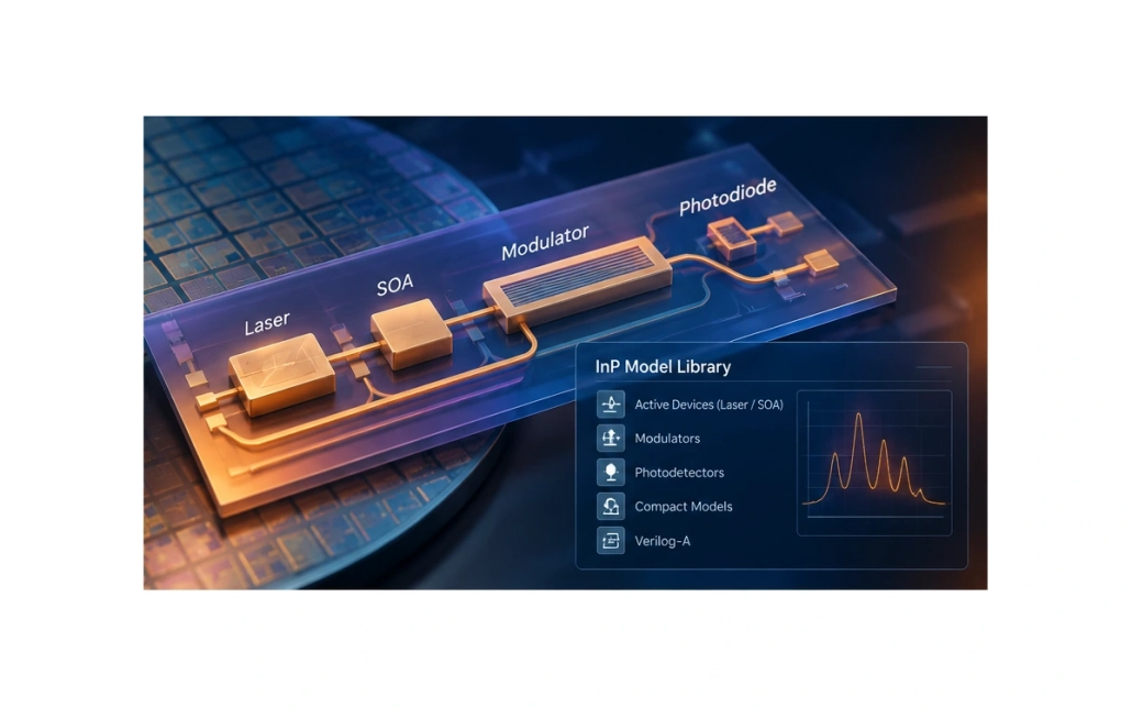
Model library for InP photonics, showing an InP chip integrating lasers, SOAs, modulators and photodetectors alongside the compact models covering those active elements

InP Photonics

PDKs with active elements

View solutions

Inputs and outputs

What you provide, and what you get

From the measurement and analysis data you collect, it generates models usable in a circuit simulator.

INPUT

What you need to prepare

Analysis results and measured valuesOutput from FDTD, MODE, CHARGE or HEAT, or measured data
Parameter definitionsThe dimensions and conditions to take as model arguments
TemplatesModel templates for each element type
Verification conditionsThe range of conditions over which the model is confirmed valid

CML Compiler

Compact model generation

OUTPUT

What you get

CML for INTERCONNECTThe compact model library used in INTERCONNECT
LibraryA distributable package containing several elements
QA test resultsComparison against the source data, regression, and verification of passivity and reciprocity
Verilog-A modelsModels and symbols for use in an EDA environment

Analysis workflow

How it works in practice

A model can never be more accurate than the data it came from. How complete you can make that source data determines the quality of the library.

01

Collect the source data for the models

Collect measured values, or FDTD, MODE, CHARGE or HEAT analysis results, for each element. Automatic data collection workflows are provided for waveguides, S-parameters, electrical phase shifters and thermal phase shifters.

02

Create the library skeleton

Generate the library source directory from a template and choose the model that suits each element.

03

Verify the data and build

Use the verification command to check the data for gaps and formatting, then generate the CML for INTERCONNECT and the Photonic Verilog-A model from the same source data. Photonic Verilog-A is generated for either Cadence Virtuoso or Synopsys OptoCompiler. Please see the latest system requirements for the releases supported.

04

Run the QA tests

Depending on the photonic model, agreement with the input data, regression, passivity and reciprocity, and consistency between frequency and time domain are all verified automatically.

05

Distribute

Version and distribute the library. In INTERCONNECT an encrypted CML is installed from Design Kits; in an EDA environment the library definition and include files are loaded.

Frequently asked questions

Questions we are often asked about CML Compiler

Questions we are often asked before adoption.

Templates are provided per element type, from passive elements through to active ones. Custom models can also be defined.

A QA testbench is generated for each element, letting you compare the response of the input data and the generated model within a tolerance you set. Depending on the photonic model, regression, passivity and reciprocity checks are also run. The reference for accuracy is the source data you supplied, so accuracy under conditions that data does not cover cannot be confirmed.

Yes. Where several designers in one organization work on the same element, keeping the model consistent is what makes comparing results meaningful.

Yes, though you need to confirm compatibility between the simulation environment you are using and the model format. In INTERCONNECT an existing CML and a CML you generated yourself can be used in the same circuit. If you use Photonic Verilog-A alongside an existing foundry PDK, check that the PDK’s model format and port conventions are supported. Note that an INTERCONNECT compact model and a Photonic Verilog-A model cannot be connected optically within the same circuit.

Japanese-language support and training

We can advise on everything from simulation setup to judging whether a result is sound. Hands-on training is also available.

Helpful to know before we talk

  • Target wavelengths and materials
  • Device structure and approximate dimensions
  • The characteristics you want to evaluate, and your target values
  • Whether you already have simulation data or measurements
  • Your expected schedule

You do not need to share everything. Whatever you are able to tell us is enough.

Try it on the problem you need to solve

The demo uses subject matter close to your own. We can also give you an idea of the configuration required and the time it takes.