ANSYS LUMERICAL / FDTD

Lumerical STACK: designing multilayer reflectance and transmittance

Obtains the reflectance and transmittance of a flat multilayer stack by the transfer matrix method. Even with many layers the calculation finishes instantly, so layer thicknesses can be optimized interactively.
Transfer matrix methodMultilayer stacksThin-film design

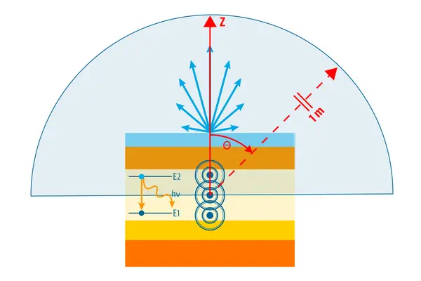
Schematic of a STACK analysis handling emission inside a multilayer stack, showing the angular distribution of light radiated by a dipole source within a layer and its extraction in the far field

Overview

For a flat layer structure, nothing is faster

If the layers are flat and laterally uniform, the fields can be treated analytically in each layer. The transfer matrix method uses that property, obtaining the whole response simply by multiplying the matrices for each layer together.

There is no numerical approximation, and the cost only scales with the number of layers. When designing antireflection coatings, mirrors and bandpass filters, a thickness sweep finishes instantly even with tens of layers.

It cannot be used for structures with a lateral pattern. Those need RCWA or FDTD.

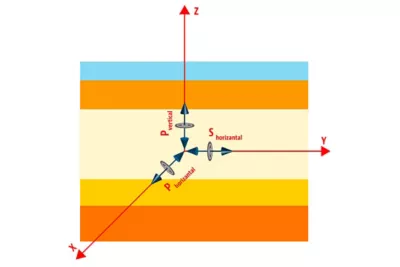
Dipole orientation in a flat multilayer structure, showing the vertically polarized and in-plane polarized components against the layer stack and each axis

What STACK gives you

What being able to assume a flat layer structure achieves

01

Analytic solution

No numerical error to worry about, and no convergence check needed.

02

Instant

Even tens of layers compute in an instant.

03

Angle and polarization

The response can be obtained directly for each angle of incidence and polarization.

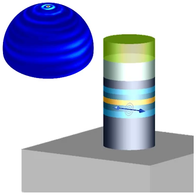
STACK solver analysis example, showing a dipole source inside a layer of a multilayer cylindrical structure alongside the far-field distribution of the light it radiates

Where it fits

Where it fits, and where it does not

For some problems another method solves faster and more accurately. The following is a guide to choosing.

Use STACK when

  • the layers are flat and laterally uniform
  • you are designing an antireflection coating or a mirror
  • you are settling the layer stack of a bandpass filter
  • you are studying the vertical layer stack of a waveguide
  • you need to evaluate the dependence on angle of incidence

Consider another method

  • There is a lateral pattern → RCWA(periodic structures)
  • Arbitrary geometry → FDTD
  • Waveguide modes → MODE

STACK compared with FDTD on the same structure. Where the layers are flat and laterally uniform, the two agree.

Typical applications

Where it is used

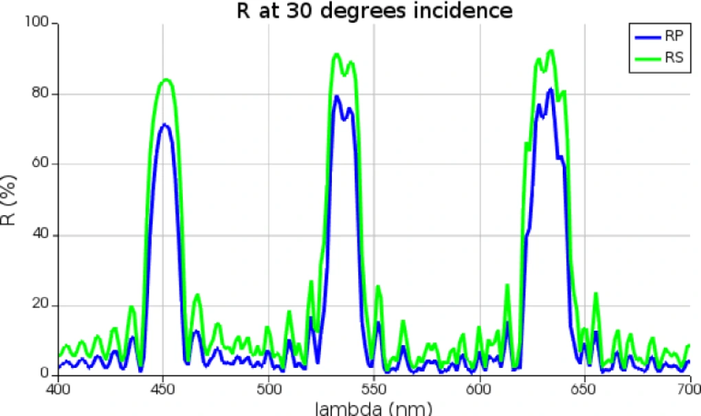
Reflectance spectrum of a dielectric multilayer stack, showing the wavelength dependence of P- and S-polarized reflectance at 30 degrees incidence

Optical thin films

Antireflection coatings and dielectric multilayer mirrors

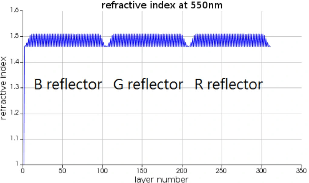
Layer stack of a dielectric multilayer, showing the refractive index of each layer at 550 nm and the groups of layers responsible for the blue, green and red reflection bands

Color filters and wavelength-selective filters

Wavelength selection by a multilayer stack, reflection and transmission characteristics, and design evaluation of color filters

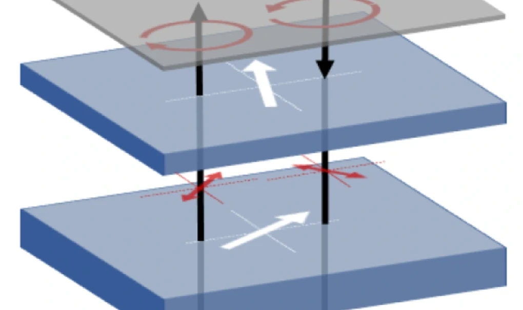
Layer stack of a circular polarizer, showing the rotation of circular polarization in the upper cover layer, the transmission axes (white arrows) and field directions (red arrows) of the two polarizing layers, and the incident and emerging light through the stack

Antireflection coatings and polarizing films

Suppressing ambient reflection with circular polarizers and multilayer stacks

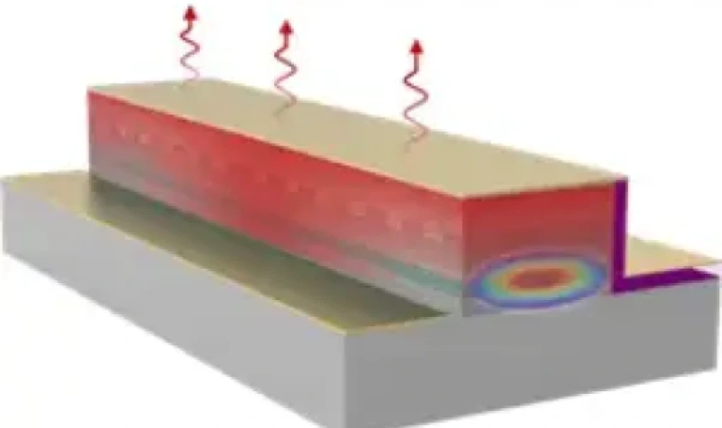
Structure of a vertical-cavity laser, showing the active layer on a multilayer substrate, wavy arrows indicating light radiated upwards, and the mode profile at the facet

Vertical cavities

DBR mirror design for VCSELs

Inputs and outputs

What you provide, and what you get

For a given layer stack and illumination conditions, it returns reflectance, transmittance and the fields within the layers.

INPUT

What you need to prepare

Layer stackThe material and thickness of each layer
MaterialWavelength-dependent complex refractive index
Excitation conditionsWavelength range, angle of incidence, polarization
SubstrateThe media on the incident and exit sides

STACK

Transfer matrix method

OUTPUT

What you get

SpectrumWavelength dependence of reflectance, transmittance and absorptance
PhasePhase on reflection and transmission
Angular dependenceResponse against angle of incidence
Distribution within layersElectric field intensity within each layer

Analysis workflow

How it works in practice

Because it is an analytic calculation, convergence is not a concern. What matters instead is judging whether the structure can be approximated as a plane-layered stack at all. Step 01 is where most of your time should go.

01

Define the layer stack

List the thickness and material (or refractive index) of each layer.

02

Set the wavelength or frequency

This setting is shared by every analysis that follows.

03

Choose the analysis type and illumination conditions

Choose between RT (plane-wave reflection and transmission), Field (field distribution within the layers), Dipole (dipole emission within a layer) and Purcell (Purcell factor), then set the angle of incidence or the dipole position.

04

Compute

This is an analytic calculation by the transfer matrix method. No mesh and no convergence run are required.

05

Evaluate the results

Extract Rs, Rp, Ts and Tp, the fields within the layers, the far-field radiation pattern and the Purcell factor. Where the structure varies laterally, switch to FDTD or another method.

Frequently asked questions

Questions we are often asked about STACK

Questions we are often asked before adoption.

There is no practical limit. The cost simply scales with the number of layers, and even tens of layers finish instantly.

Yes. Specify a complex refractive index.

Yes, although STACK on its own has no dedicated thickness-optimization feature. You compute spectra with a script such as stackrt and search for thicknesses close to the target spectrum using parameter sweeps or optiSLang.

STACK if the structure is laterally uniform, RCWA if there is a periodic pattern. RCWA can handle flat layers too, but STACK is simpler and faster.

Japanese-language support and training

We can advise on everything from simulation setup to judging whether a result is sound. Hands-on training is also available.

Helpful to know before we talk

  • Target wavelengths and materials
  • Device structure and approximate dimensions
  • The characteristics you want to evaluate, and your target values
  • Whether you already have simulation data or measurements
  • Your expected schedule

You do not need to share everything. Whatever you are able to tell us is enough.

Try it on the structure you actually need to solve

The demo uses a structure close to your own. We can also give you an idea of the computational scale and the time it takes.