
Home/Analysis Technologies/Optical analysis/Non-Sequential Ray Tracing

Analysis Technologies | Optical Analysis

Non-Sequential Ray Tracing

A method that assumes no order in which surfaces are passed and decides the next intersection from the position and properties of the objects and the direction of the ray alone.

Target

Systems where the ray path is set by geometry

Tracing

Forward Monte Carlo ray tracing

Supporting products

Ansys Zemax OpticStudio
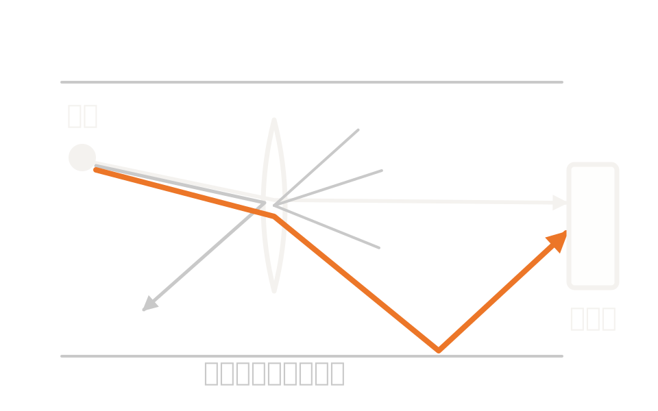
Schematic showing rays intersecting objects arranged in three dimensions, refracting, splitting and scattering repeatedly, with the paths accumulating on a detector

What the method is

Geometry decides the path, not an order

Objects are placed as surfaces or solid bodies, each with its own position and orientation in absolute coordinates. Which object a ray strikes, and where, is decided by the position and properties of the objects and the direction of the ray alone. A ray may strike the same object any number of times, or none at all.

At an interface a ray can be split into reflected and transmitted components. That splitting requires polarization calculation. As an alternative to splitting, there is also the option of randomly choosing either reflection or transmission with probability proportional to each component, which amounts to Monte Carlo branch selection. At a scattering surface, the number of scattered rays you set is generated.

The number of rays is specified per source. Analysis and layout ray counts are held separately, so the clarity of the diagram and the accuracy of the analysis can be managed independently.

How it works

Find intersections, split, accumulate

No path is entered. From its current position and direction, a ray looks for the next object it intersects and reflects, refracts or scatters according to the optical properties of that surface. This repeats until a termination condition is met, and the result accumulated over many rays is the distribution on the detector.

That way of accumulating is why it is called forward Monte Carlo ray tracing. Splitting and scattering branch the rays, so the number of segments arising from one ray grows rapidly. That is why there are limits on intersections and segments per ray, with a ray terminated where it reaches the limit.

Intersection testWhich object is struck next is decided by the position and properties of the objects and the direction of the ray alone. The user never supplies a surface order.
SplittingTo split a ray into both reflected and transmitted components at an interface, polarization calculation has to be enabled.
Probabilistic selectionInstead of splitting, either reflection or transmission can be chosen with probability proportional to the component ratio. Many rays are traced and the results accumulated.
ScatteringScattering at a rough surface is given as a bidirectional scattering distribution function, generating the number of scattered rays you set from each incident ray.

Strengths of this method

Why this method is chosen

Paths you did not anticipate appear too

Because no surface order is supplied, paths the designer never anticipated, such as multiple reflection, total internal reflection and scattering from mechanical parts, appear in the result as they are.

Surface properties from measurement

Lambertian scattering, Gaussian scattering, the ABg model, tabulated BSDF data and user-defined models can be assigned per surface, so roughness and paint effects can be handled from measured values.

Concentrating rays on the target

Importance sampling, which always scatters toward the target, greatly increases the number of rays reaching it for the same run time. Intensity is weighted by the mean of the scattering distribution within the solid angle the target subtends.

Where it fits

Where it fits, and where it does not

Where it is a good fit

→ when handling systems where the order light passes through cannot be fixed in advance, such as illumination systems and light guide plates

→ when the system includes prisms, corner cubes, light pipes or geometry imported from CAD

→ when you need to include multiple reflection, total internal reflection and scattering from mechanical parts

→ when you want to identify stray light paths exhaustively

Where another method is the better fit

Imaging systems with a defined surface order: imaging and afocal systems that proceed in order from object plane to image plane are the territory of sequential ray tracing.

Propagation of coherent fields: in systems containing elements where no path is assumed, the accuracy of complex amplitude propagation is generally not guaranteed. Use physical optics propagation on an equivalent model that does assume surface order.

Getting a first read on ghosts: if you only want to know quickly which combinations of surfaces matter, an inventory of single and double reflections assuming surface order is faster.

The effect of assembly variation: to see the spread of performance against errors, set it up as a tolerance analysis.

Applications

Typical applications

Illumination systems

Design the illuminance distribution and light distribution from source to detector.

Light pipes and prisms

Handle elements that guide light by total internal reflection and multiple reflection.

Stray light in camera modules

Evaluate ghosting and scattering, including reflection from the detector surface itself.

Systems dominated by scattering

Evaluate with measured scattering data or ABg coefficients applied to the surfaces of mechanical parts.

Inputs and outputs

What you provide, and what you get

INPUT

Three-dimensional geometry Optical elements and mechanical parts, including geometry imported from CAD
Light source From point sources to three-dimensional emission distributions. Analysis and layout ray counts are specified separately
Surface properties Coatings and scattering models (Lambertian, Gaussian, ABg, BSDF, user-defined)
Trace settings Enabling splitting and polarization, and the limits on intersections and segments per ray

OUTPUT

Distribution on the detector Incoherent illuminance, coherent illuminance, coherent phase
Radiometric and photometric quantities Radiant intensity, radiance, and photometric results including color
Volume distribution The distribution of luminous flux accumulated in three-dimensional voxels
Path data Ray paths that can be filtered by condition, so the largest contributors can be identified

How it works

How it works in practice

01

Build the three-dimensional model

Place sources, optical elements, mechanical parts and detectors in three-dimensional space. Conversion from a model assuming surface order is also possible.

02

Assign surface properties

Give each surface a coating and a scattering model. Where a target is hard to reach, specify it for importance sampling.

03

Enable splitting and scattering, and trace

Enable ray splitting and polarization, raise the limits on intersections and segments to the level needed, and trace.

04

Break the paths down and read them

Check the distribution on the detector, then filter the paths to identify the largest contributors.

Enabling splitting and scattering makes the segment count grow sharply, and a ray that reaches the limit is terminated there. A trace run without raising the limits cannot be trusted. Step 03 is where most of your time should go.

Comparison with related methods

Choosing between related analysis methods

Method Relationship Main targets When to use which
Non-sequential ray tracing (this method) This method Systems where the ray path is set by geometry Intersections are decided by object placement and ray direction alone, and reflection, refraction, splitting and scattering are handled as they are and accumulated on the detector.
Sequential Ray Tracing Alternative Imaging systems with a defined surface order On the premise that each surface is passed once in order, runs aberration evaluation and optimization quickly.
Stray Light Analysis Downstream Identifying unintended paths An approach built on this trace, combining splitting, scattering, importance sampling and path filtering.
Physical Optics Propagation (POP) Complementary Propagation of coherent fields Propagates a complex amplitude field rather than accumulating flux along rays. In systems containing elements where no path is assumed, accuracy is not guaranteed.
Tolerance Analysis Downstream Performance variation against tolerances In systems where no path is assumed, the effect of errors is estimated against a merit function built from detector values.

View all analysis technologies →

Supporting products

Products that provide this method

Non-sequential ray tracing is provided as one of this product’s analysis modes. Conversion from a model assuming surface order, and systems combining the two, are also supported. See here for licensing, system requirements and deployment.

Ansys Zemax OpticStudio

View the product page →

FAQ

Frequently asked questions

How many rays do I need?The number needed depends on the quantity you are evaluating and the accuracy you require. The published material we consulted gives neither a recommended count nor a convergence criterion, so increase the count and confirm for yourself that the result settles. Weak signals such as stray light need particularly many rays.
What is required for ray splitting?To generate both reflected and transmitted components at an interface, polarization calculation has to be enabled. Without it, either reflection or transmission is chosen with probability proportional to the component ratio.
Can CAD data be imported?Yes. Imported geometry can be placed as objects as it is, so models including the barrel and mechanical parts can be built.
Can I convert from a model that assumes surface order?Yes. A system designed assuming surface order can be converted into objects, and the two can also be combined into one system as a group with entry and exit ports.

References

Last updated

2026-08-18

Technical review

LightBridge Technical Support

Sources consulted

Ansys Zemax OpticStudio 2025 R1 User Guide (Available Scatter Models)Exploring Non-Sequential Mode in OpticStudio (Ansys Optics knowledge base)Exploring Sequential Mode in OpticStudio (Ansys Optics knowledge base)How to use importance sampling to model scattering efficiently (Ansys Optics knowledge base)Stray Light Analysis Overview (Ansys Optics knowledge base)

We can advise on illumination, stray light and complex optical path analysis

Tell us the make-up of the system and the metrics you want to evaluate, and we will propose the method and the way forward.