Home/Analysis Technologies/Performance evaluation/Stray Light Analysis

Analysis Technologies | Performance Evaluation

Stray Light Analysis

An approach that models light reaching the image plane by paths other than the designed one, including ghosting, coatings, scattering and mechanical parts, and breaks it down path by path.

Target

Light travelling unintended paths

How it works

Ghost inventory, with splitting and scattering traced

Supporting products

Ansys Zemax OpticStudio

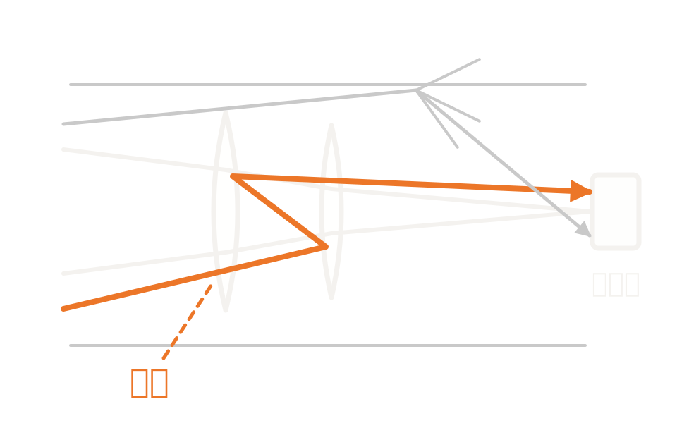
Schematic showing, alongside the intended rays, the paths by which ghosting, scattering from the inner barrel and light from the edges of mechanical parts reach the detector

What the method is

Not a single feature but a way of putting things together

Stray light means light that reaches the image plane without travelling the designed path. It arises in two broad ways: light from a strong source outside the field scattering off mechanical or optical parts and reaching the image plane, and light within the field reflecting several times at lens surfaces and forming a ghost image.

Stray light analysis does not exist as a standalone analysis feature. It is a procedure combining a trace that assumes no path with ray splitting and scattering enabled, per-surface scattering models, importance sampling, and path filtering after the trace.

A trace assuming surface order can also produce an inventory of single and double reflection ghost paths by replacing refractive surfaces with reflective ones. That is only a first estimate, though. Including multiple reflection, total internal reflection and stray light originating in mechanical parts requires a trace that assumes no path.

How it works

Model the sources, reflections, scattering and paths of unwanted light

Unwanted light does not come from one mechanism. Ghosting from specular reflection at surfaces, reflection and transmission at coatings, scattering at rough surfaces and mechanical parts, and multiple and total internal reflection all overlap so that light not travelling the designed path reaches the image plane. The model therefore has to include the barrel and mechanical parts as well as the optical elements, and you also confirm that chief and marginal rays pass the apertures as intended.

Scattering is given as a bidirectional scattering distribution function. Per surface, choose from Lambertian scattering, Gaussian scattering, the ABg model, tabulated scattering data and user-defined models. The ABg model is written as a function of direction cosines, a form suited to scattering from isotropic surface roughness.

From the theory side, scattering at a rough surface can be formulated as a linear system in direction-cosine space. Under the condition that the surface is smooth enough, the scattering function is proportional to the power spectral density of the surface roughness. The translational invariance of that formulation does not hold universally, however, and it has been shown that a different transfer function is needed for each angle of incidence. Scattering characteristics measured at one angle of incidence cannot simply be extrapolated to another.

Separating the mechanismsScattering from a strong source outside the field, and ghosting where light within the field reflects multiple times between surfaces. Start by taking an inventory of the two mechanisms separately.
Path splitting and coatingsSplitting a ray into reflected and transmitted components at an interface lets partial and multiple reflection be followed at once. Splitting requires polarization calculation, and the main means of reducing the effect of ghosting is the coating on each surface.
Describing scattering, and its dependence on angle of incidenceScattering at a rough surface is given as a bidirectional scattering distribution function. Under the condition of a smooth surface it can be related to the power spectral density of the surface roughness, but because the transfer function differs with angle of incidence, extrapolating characteristics measured at one angle to another is not generally justified.
Importance samplingBy always scattering toward the target and weighting the intensity by the mean of the scattering distribution within the solid angle the target subtends, the number of rays reaching it increases while radiometric correctness is preserved.

Strengths of this method

Why this method is chosen

Weak paths become visible

Importance sampling, which always scatters toward the target, greatly increases the number of rays reaching it for the same run time. Because intensity is weighted by the mean of the scattering distribution within the solid angle, radiometric correctness is preserved.

Causes can be named as paths

Because paths can be filtered after the trace, you can identify which combination of surfaces, and which mechanical part, is responsible.

Measured values can be brought in

Scattering characteristics can be given as tabulated data or ABg coefficients, so measured surface properties go straight into the analysis.

Where it fits

Where it fits, and where it does not

Where it is a good fit

→ when light from a strong source outside the field could reach the image plane by scattering off mechanical or optical parts

→ when light within the field reflects several times at lens surfaces and forms a ghost image

→ when you want to name which combination of surfaces, or which part, dominates

→ when you want to estimate the effect of an antireflection coating or baffling before committing to it

→ when surface roughness moves a non-negligible fraction from the specular component into scattering

Where another method is the better fit

Imaging performance at nominal values: refining aberrations and MTF with neither errors nor unintended paths included is handled by sequential ray tracing.

Designing the light distribution itself: if the aim is to shape the illuminance distribution or light distribution, the approach is non-sequential ray tracing.

Propagation of coherent fields: propagation dominated by diffraction is the territory of physical optics propagation. It does not replace a stray light trace, though, because accuracy is not guaranteed in systems containing elements where no path is assumed.

Scattering at wavelength scale: scattering and diffraction from a fine structure itself is obtained by electromagnetic analysis, and that result is then given as the surface scattering property.

Applications

Typical applications

Camera modules

Evaluate ghosting including reflection from the detector surface itself, and image degradation in backlit conditions.

Spectrometers

Identify the stray light paths that govern measurement accuracy.

Space and remote sensing

Evaluate the effect of a strong out-of-field source such as the sun.

Automotive lighting and cameras

Check degradation in appearance caused by reflection inside the housing.

Inputs and outputs

What you provide, and what you get

INPUT

Three-dimensional model The whole assembly, including the barrel and mechanical parts as well as the optical elements
Coatings Antireflection coatings per surface. The main means of suppressing ghosting
Scattering properties Scattering model and coefficients per surface. Measured values are supplied from a file
Trace settings Enabling splitting and polarization, the limits on intersections and segments, and the importance sampling targets

OUTPUT

Distribution on the detector The spatial distribution of stray light on the detector
Ghost inventory A list classified into pupil ghosts and image ghosts, with ray heights and focus positions
Contribution per path The filtered paths, ranked by contribution
Critical ray check Confirmation that the chief and marginal rays of each field pass as intended

How it works

How it works in practice

01

Take an inventory of ghost paths

With surface order assumed, replace refractive surfaces with reflective ones and establish the single and double reflection ghosts, separated into pupil ghosts and image ghosts.

02

Move to a model that assumes no path

Add the barrel and mechanical parts to the converted optical system, and assign a coating and a scattering model to each surface.

03

Enable splitting and scattering, and trace

Enable polarization calculation and ray splitting, and raise the limits on intersections and segments. Set importance sampling for targets that are hard to reach.

04

Filter the paths and act on them

Identify the largest contributors and reduce their effect by revising the geometry or changing the coating.

The inventory in step 01 is a first estimate assuming every surface has the same coating. Enabling splitting and scattering makes the segment count grow sharply, and a ray that reaches the limit is terminated there. Step 03 is where most of your time should go.

Comparison with related methods

Choosing between related analysis methods

Method Relationship Main targets When to use which
Stray light analysis (this method) This method Identifying and quantifying unintended paths Models ghosting, coatings, scattering and mechanical parts, and breaks the contribution down path by path.
Non-Sequential Ray Tracing Upstream The path-free trace itself Stray light analysis is an approach built on this trace. The trace itself is also used to design illuminance and light distribution.
Sequential Ray Tracing Upstream A first estimate assuming surface order, and supplying the model Replaces refractive surfaces with reflective ones to take an inventory of single and double reflection ghosts, and that design is then converted and brought across. Stray light from multiple reflection or mechanical parts cannot be handled at this stage.
Physical Optics Propagation (POP) Complementary Propagation of coherent fields Propagates a single complex amplitude field rather than accumulating flux along many split rays.
Tolerance Analysis Complementary Performance variation against tolerances Handles the spread of intended performance. Making detector values the merit function brings variation in stray light within scope too.

View all analysis technologies →

Supporting products

Products that provide this method

Stray light analysis proceeds by combining this product’s ray splitting, scattering models, importance sampling and path filtering. It is not carved out as a standalone feature. See here for licensing, system requirements and deployment.

Ansys Zemax OpticStudio

View the product page →

FAQ

Frequently asked questions

Is there a metric for the amount of stray light?Definitions of quantitative metrics such as point source transmittance or veiling glare are not given in the published Ansys material we consulted. This page therefore gives neither a definition nor a figure. What you judge acceptance against is something to discuss case by case, according to the target and the requirement.
What if there is no measured scattering data?Relative comparison using representative models is possible. Once a coefficient is assumed, though, absolute quantities cannot be claimed. If you need absolute values, obtain measured data.
Can scattering characteristics be used at a different angle of incidence?Generally not. It has been shown theoretically that the scattering transfer function differs with angle of incidence. If you extrapolate characteristics measured at one angle to another, state that assumption explicitly.
How do I move across from a design that assumes surface order?Use the conversion feature to move to a model that assumes no path, then add the barrel and mechanical parts. Where evaluation of the whole system is needed, there is also a route for passing the optical design data to Ansys Speos.

References

Last updated

2026-08-18

Technical review

LightBridge Technical Support

Sources consulted

Ansys Zemax OpticStudio 2025 R1 User Guide (Available Scatter Models)Stray Light Analysis Overview (Ansys Optics knowledge base)Introduction to stray light analysis – Part 1 (Ansys Optics knowledge base)Introduction to stray light analysis – Part 2 (Ansys Optics knowledge base)Stray Light Analysis with Ghost Focus Generator (Ansys Optics knowledge base)What scattering models are available in OpticStudio? (Ansys Optics knowledge base)

We can advise on identifying the cause of stray light

Tell us how the optical system and housing are put together and the symptom you are seeing, and we will propose how to evaluate it.