Home/Analysis Technologies/Optical analysis/Polarization Analysis

Analysis Technologies | Optical Analysis

Polarization Analysis

A capability that extends ray tracing by giving each ray a complex electric field vector, and evaluates how reflection and absorption at coatings and interfaces affect polarization state and transmittance. Isotropic interfaces and birefringent media are handled differently. It is not a standalone solver.

Where it sits

An analysis capability extending ray tracing

Quantity handled

A complex electric field vector per ray

Supporting products

Ansys Zemax OpticStudio

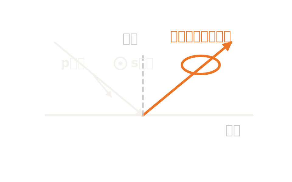
Diagram showing the electric field vector resolved into s and p components at an interface, multiplied by complex coefficients and reassembled

What the method is

Carrying an electric field vector on the ray

In OpticStudio, polarization analysis is positioned as an extension of ordinary ray tracing. It takes into account the effect of optical coatings and of loss by reflection and absorption on how light propagates through the system. It does not solve the field equations separately: the rays traced are the same.

Ordinary ray tracing does not handle the change in field amplitude and phase that depends on angle of incidence, incident polarization, the media on either side of an interface, and the properties of the coating. To handle that, this capability gives each ray an electric field vector with complex components and transforms it at each interface.

The incident polarization is given as a Jones vector. Because a two-component Jones vector has to be converted into the three-component field of a ray with arbitrary direction, there is a setting for the reference axis. In fast-converging systems the reference orientation changes with position in the pupil, so you need to check that the polarization is what you intended.

How it works

At an isotropic interface, resolve into s and p components and apply complex coefficients

A constraint is imposed that the electric field vector must be orthogonal to the ray propagation vector. At isotropic interfaces and coatings, the field is resolved into s and p components with reference to the plane of incidence formed by the ray vector and the surface normal. The s component is the projection along the axis orthogonal to the plane of incidence, the p component the projection within it.

Each resolved component is multiplied by a complex transmission or reflection coefficient. Because the coefficients are complex, both amplitude and phase change. They are computed from the refractive index of the incident medium, the index and thickness of each coating layer, and the index of the substrate. After multiplication, the two components are reassembled into a Cartesian field vector and proceed to the next surface. Where a ray travels normal to a surface the distinction between s and p becomes ambiguous, which is why a reference axis setting is needed.

That resolution and application of coefficients is the treatment for isotropic interfaces and coatings. Not all polarization calculation proceeds this way. Birefringent media are handled between dedicated entry and exit surfaces, with ordinary and extraordinary rays traced separately. Which is traced, or whether one is traced while the phase rotation from the other is taken into account, is a mode setting. Where an ideal polarizing element is represented by a Jones matrix surface, a two-by-two complex matrix acts directly.

Defining the incident polarizationGiven as the two components of a Jones vector with their phases. There is a setting applied system-wide and one given per analysis.
Choosing the reference axisChoose which axis is the reference when building a three-component field from two components. In fast-converging systems the orientation changes with position in the pupil.
Transformation at an isotropic interfaceAt isotropic interfaces and coatings, the field is resolved into s and p components with reference to the plane of incidence, multiplied by complex reflection and transmission coefficients, and reassembled.
Handling birefringence and polarizing elementsBirefringent media are placed between dedicated entry and exit surfaces, with ordinary and extraordinary rays traced separately. Ideal elements are represented by a Jones matrix surface and real films by a coating. Each proceeds differently in the calculation.

Strengths of this method

Why this method is chosen

Transmittance followed with polarization included

Relative and cumulative transmittance per surface, and the integrated transmittance of the whole system, can be obtained per field and wavelength. Transmission through the preceding material and through the interface coating are both taken into account.

Polarization state can be visualized

The polarization ellipse can be plotted by position in the pupil. Major and minor axis lengths, the azimuth of the major axis, the phase difference between components and the intensity are also available numerically.

It connects to design

Coating and polarization ray-trace data can be used as merit function operands, so polarization performance itself can be a target of optimization.

Where it fits

Where it fits, and where it does not

Where it is a good fit

→ when you need transmittance and reflectance per polarization in a system with coatings

→ when you want to follow the change in polarization state surface by surface in a system with polarizers or waveplates

→ when you want to see how polarization state varies across the pupil

→ when you want to evaluate phase changes arising from polarization

→ when you want to design with polarization or coating performance in the merit function

Where another method is the better fit

Wavelength-scale fine structures: this method puts an electric field vector on a ray and multiplies by interface coefficients. Diffraction orders, resonance and near fields lie outside a geometric ray model. Obtain the response of a grating or meta-atom with an electromagnetic solver and bring that result into the ray trace.

Polarization ellipses for strongly tilted rays: the polarization pupil map presumes rays are nearly parallel to the Z axis and ignores the Z component of the field. For rays strongly tilted from the Z axis, the interpretation of that plot does not hold.

Oblique incidence on a Jones matrix surface: a Jones matrix surface does not define the treatment of the Z field component, which means it presumes an ideal polarizing element placed in a collimated beam. To include real coefficients and absorption at oblique incidence, use a coating or birefringent entry and exit surfaces.

Propagation including diffraction: where the field itself has to be carried from surface to surface rather than rays, move to physical optics propagation.

Applications

Typical applications

Systems with a polarizing beamsplitter

Separate the reflected and transmitted polarizations and evaluate transmittance and polarization state per path.

Waveplate and retarder design

Confirm from the thickness and axis orientation of the birefringent medium that the retardance is what you intended.

Polarization tracing with scattering

Handle polarization-dependent volume scattering and follow how polarization and direction change at each scattering event.

Working with metasurfaces

Bring in the polarization-dependent response obtained with an electromagnetic solver and evaluate whole-system performance.

Inputs and outputs

What you provide, and what you get

INPUT

Incident polarization The two components of a Jones vector with their phases. A setting that uses no polarization is also available
Reference axis The axis used as reference when building a three-component field from a two-component polarization
Coatings The material, complex refractive index and thickness of each layer. Layer coefficients and index corrections can also be design variables
Material The indices of the incident medium and substrate, and transmittance within the medium. For birefringence, the material pair for ordinary and extraordinary rays
Surface settings Jones matrix surfaces, birefringent entry and exit surfaces, and the shape and aperture of ordinary surfaces
Ray specification Field coordinates, pupil coordinates, wavelength number, surface number, sampling density

OUTPUT

Transmittance The integrated transmittance of the whole system, and relative and cumulative transmittance per surface
Polarization state The polarization ellipse by position in the pupil, with its major axis, minor axis and azimuth
Field values Each field component and its phase, the phase difference between components, and the intensity
Phase from polarization The distribution across the pupil of phase arising from polarization
Interface coefficients Reflectance and transmittance for s and p polarization, diattenuation and retardance

How it works

How it works in practice

01

Give the system its polarization physics

Assign coatings to the surfaces. Ideal polarizing elements are represented by Jones matrix surfaces, and birefringent media are placed between entry and exit surfaces.

02

Settle the incident polarization and reference axis

Give the two Jones vector components and their phases and choose the reference axis. Decide whether it applies system-wide or per analysis.

03

Check the transformation

Open the polarization ray trace listing for representative rays and confirm that the polarization you gave has been converted into the field you intended.

04

Evaluate

Evaluate the polarization state across the pupil, transmittance for the whole system and per surface, the variation of transmittance with pupil position, and the phase arising from polarization.

Do not skip step 03. In fast-converging systems the s and p directions change with position in the pupil, so the choice of reference axis changes the polarization state each ray carries. Transmittance computed with polarization off is the average of two orthogonal polarizations and is not affected by that choice.

Relationship to related methods

Division of roles and coupling with related analysis methods

Method Relationship Main targets When to use which
Polarization analysis (this method) This method Change of polarization at coatings and interfaces Puts a complex electric field vector on the ray and, at each interface, resolves it into s and p components and multiplies by complex coefficients. Evaluates transmittance and polarization state.
Sequential Ray Tracing Upstream Tracing systems where surface order can be assumed The capability that performs the trace itself. This capability layers a field vector transformation on top of that trace.
Physical Optics Propagation Complementary Propagation including diffraction Carries a complex amplitude field from surface to surface rather than rays. Used where diffraction, not polarization, is the question.
RCWA Upstream Wavelength-scale periodic structures Obtain the polarization-dependent response of a grating or meta-atom with an electromagnetic solver, then bring that result into the ray trace.

View all analysis technologies →

Supporting products

Products that provide this method

Commercial software used for the design and analysis of imaging, illumination and laser systems. It provides polarization ray tracing, coatings and birefringence handling, and continues through optimization and tolerance analysis in the same environment. See here for licensing, system requirements and deployment.

Ansys Zemax OpticStudio

View the product page →

FAQ

Frequently asked questions

Is this a solver?No. It is a capability extending ordinary ray tracing to take into account the effect of coatings and of loss by reflection and absorption. It does not discretize and solve Maxwell’s equations.
Which reference axis should I choose?The default uses the X axis as reference. For non-parallel rays, though, the s and p directions change with position in the pupil. Always confirm in the polarization ray trace listing that the conversion from Jones vector to field is what you intended.
Can I always use the polarization ellipse plot?No. The polarization pupil map presumes rays are nearly parallel to the Z axis and ignores the Z field component. It does not hold for rays strongly tilted from the Z axis. The transmittance shown on the same screen, however, is computed with the Z component included.
How do I place an ideal polarizer?A Jones matrix surface is provided. A two-by-two complex matrix can represent a polarizer or waveplate, but because the treatment of the Z field component is undefined, it presumes placement in a collimated beam. To include real coefficients and absorption at oblique incidence, use a coating or birefringent entry and exit surfaces.

References

Last updated

2026-08-19

Technical review

LightBridge Technical Support

Sources consulted

Ansys Zemax OpticStudio User Guide: Polarization AnalysisAnsys Zemax OpticStudio User Guide: The Electric Field VectorAnsys Zemax OpticStudio User Guide: Defining the Initial PolarizationAnsys Zemax OpticStudio User Guide: Polarization Pupil MapAnsys Zemax OpticStudio User Guide: Polarization Ray TraceAnsys Zemax OpticStudio User Guide: TransmissionAnsys Zemax OpticStudio User Guide: Definition of Polarization TermsAnsys Optics: Investigating OpticStudio’s polarization featuresAnsys Optics: How to use the Jones Matrix surfaceAnsys Optics: Polarization-sensitive scattering in OpticStudio

We can advise on evaluating optical systems that involve polarization

Tell us how the system is put together and the polarization symptom you are seeing, and we will propose how to evaluate it.